Modeling the Terrain
Editing the Elevation
In this section, we are going to learn about the tools from the Site tool set that help you change the elevation of particular areas of the terrain surface.
The functionality described in this section is only available in the Pro edition.
These tools are available when the Site layer is activated. What you create with these tools take effect only inside the terrain outline.
Multiple Elevation objects can be used together to create a terrain with complex topography.
Explicit and Calculated Elevation
Considering the whole terrain area, you will be able to define the elevation of a tiny amount of points. The elevation of the rest will be calculated.
In the following illustration, there is the terrain outline at the top and the terrain side view at the bottom. Pairs of diamond-shaped points 1 and 1', 2 and 2' and others have the same elevation. They make the terrain look like a rice field terrace. The arrows show points on the side view that correspond to 1-6. While the elevation at points 1-6 is determined by the user, the elevation in the middle (A, B, C and D) is calculated to have gradual transitions from 1 to 2, 2 to 3 and so forth.
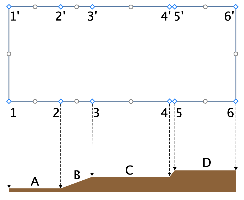
Let's suppose that you need to set a particular elevation at point C. In this case, you either add more points on the terrain outline or add an Elevation Line, Path or Point using the tools described below.
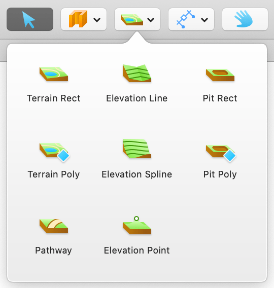
The Elevation Line and Elevation Spline Tools
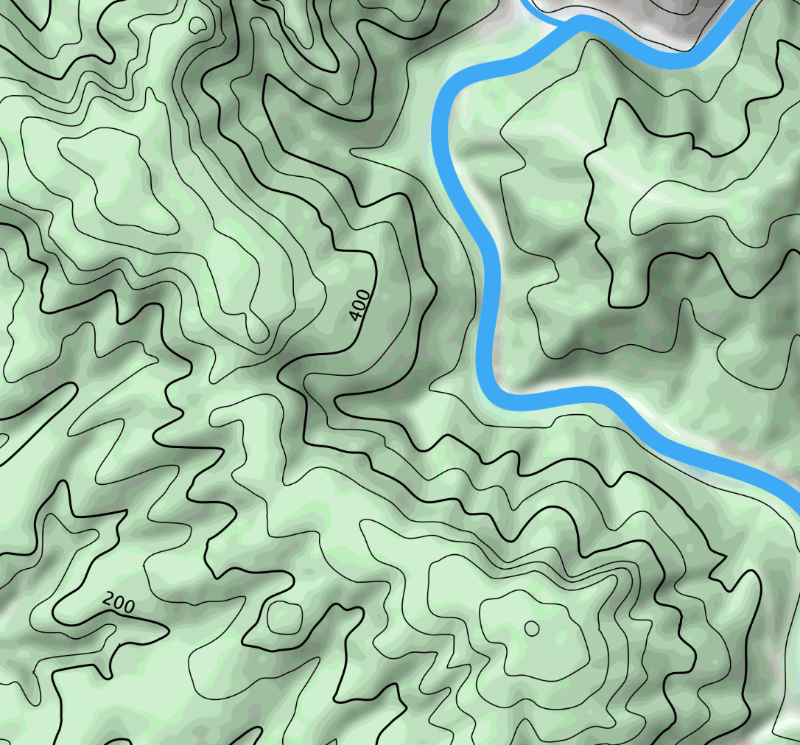
The Elevation Line and Elevation Spline tools let you draw lines that link points with the same elevation. These lines are called elevation contour lines, exactly the kinds of lines you can see on a topographic map.
The Elevation Line tool creates straight lines, while the Elevation Spline tool works like a freehand tool in graphics software.
To draw a straight line, activate the Elevation Line tool. Then click once where the line should begin. Finally, double-click where the line should end.
To draw a multi-segment line or polygon, click with the Elevation Line tool where the line should begin. Click several more times to add more segments. Double-click to set the end of the last segment and stop drawing.
To draw a curved line, activate the Elevation Spline tool. Press the left mouse button to start drawing. Release the button to stop drawing.
A solid line indicates that it is closed (its beginning and end coincide). A dashed line indicates that it is open.
Adding a shape like a rectangle or circle with certain elevation would create a sort of plateau.
Properties of the Elevation Line and Elevation Spline Objects
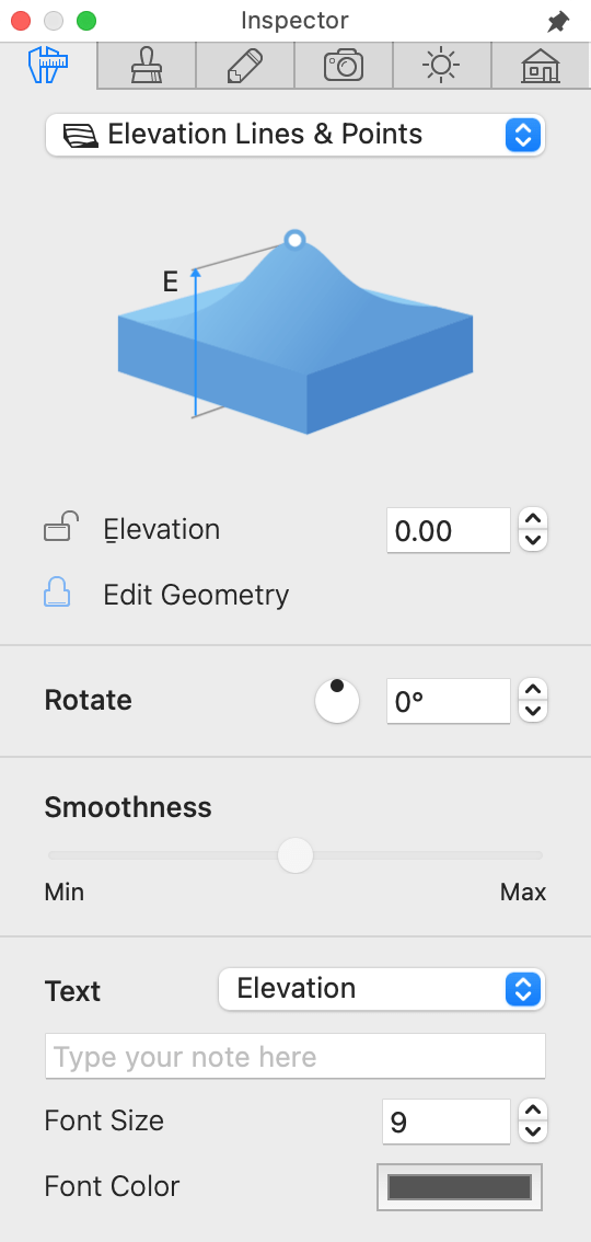
Properties of the Elevation Line or Elevation Spline objects can be found in the Object Properties tab of the Inspector.
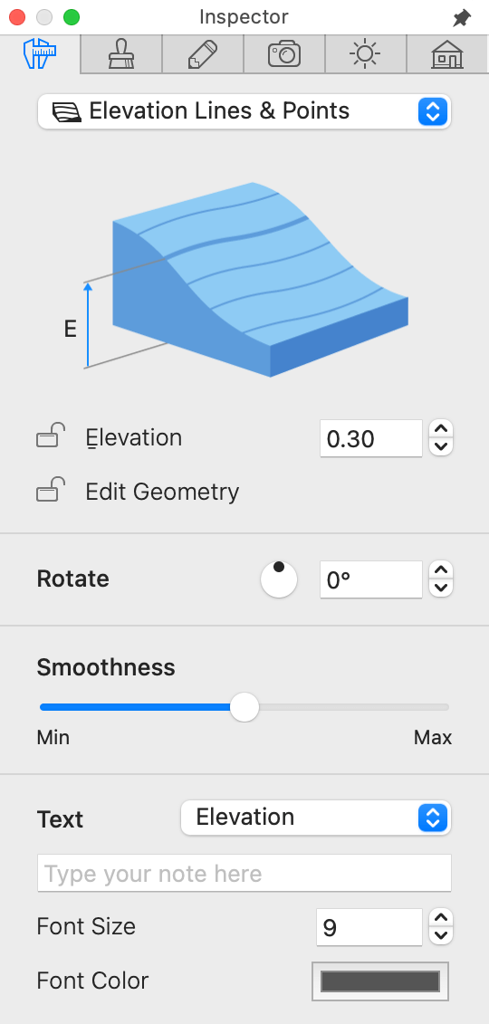
The Elevation parameter defines the elevation of the specified area above the ground level.
The Edit Geometry option allows or disallows modifying the shape of the line by double-clicking on it. When the option is locked, you can still activate the edit mode by right-clicking on it in the 2D view and choosing Edit Contour.
The Rotate controls change the object's orientation.
The Smoothness slider changes how curved sides of an object look in 3D. At the Min position, the 3D shape is approximated with a smaller number of larger facets. This improves the program performance, but makes the shape less accurate.
A group of controls at the bottom of the Inspector lets you set up a text label. You can choose what kind of information to display (e.g., elevation or your own text), and you can also set the font size and color.
Note that it is possible to drag the text label to a new location.
Edit the Shape of a Line
To edit the 2D shape of an Elevation Line or Elevation Spline object, right-click on it and select Edit Contour from the context menu. Alternatively, you can double-click on the object in the 2D Plan view.
In the edit mode, a line hides its label and displays two types of handles: diamond-shaped and circular.
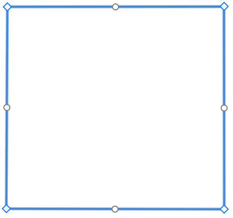
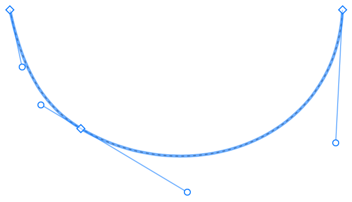
Diamond-shaped handles coincide with points through which the line passes. In the case of an open path, two of the points define the two ends of the line. In order to edit the shape of the line, drag a diamond-shaped handle to a new location. To add or delete a point, right-click on the line and select the corresponding command from the context menu.
Circular handles are used to change the curvature of a line segment between two points.
Once an Elevation Line or Elevation Spline has been drawn, you can continue drawing it later at one or another end. This is possible if the line is not closed (has free ends). To do that, select an existing line with the Selection tool. Then activate the Elevation Line or Elevation Spline tool. Place the cursor over one of the line ends. Finally, draw a new part of the line.
The Elevation Point Tool
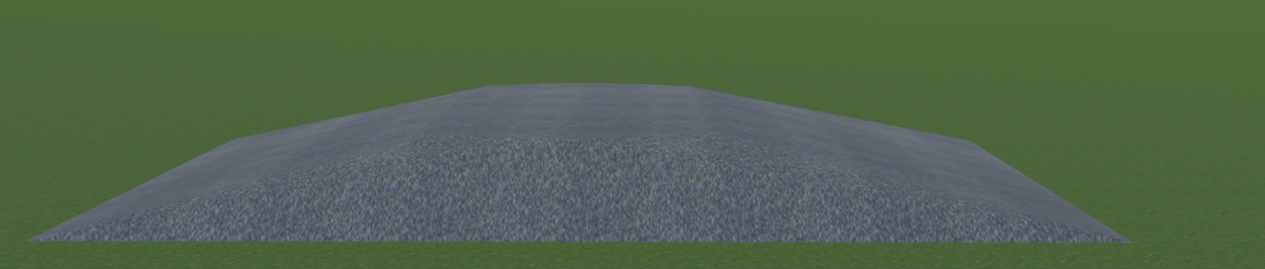
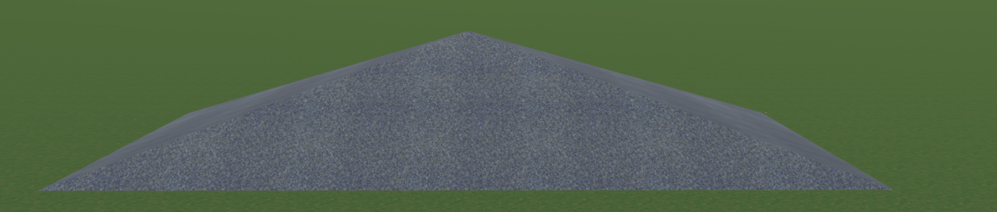
The Elevation Point tool defines the elevation of a small spot. It may look like a peak if it is placed in the middle of the terrain.
In order to add an Elevation Point, activate the Elevation Point tool. Then click at some point in the 2D Plan view.
To relocate the point, just drag it to a new place.
Properties of the Elevation Point Object
Properties of the Elevation Point object can be found in the Object Properties tab of the Inspector.
The Elevation parameter defines the point's elevation above the ground level.
A group of controls at the bottom of the Inspector lets you set up a text label. You can choose what kind of information to display (e.g., elevation or your own text), and you can also set the font size and color.
The Pit Rect and Pit Poly Tools
The Pit Rect and Pit Poly tools let you define an area below the ground level.
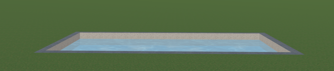
To add a rectangular pit, draw it on the floor plan with the Pit Rect tool. Click and hold down the mouse button to start drawing a rectangle. You should then move the cursor to a new position and release the button.
To draw a polygonal pit, activate the Pit Poly tool. Click several times on the floor plan to add corners. Double-click in order to specify the position of the last corner of the polygon and deactivate the tool.
In order to change the outline of a pit, double-click on it. This will show handles that you can move to relocate the object's corners. Editing the outline of a pit is similar to editing a terrain explained in the Customize the Outline of a Terrain section.
Properties of the Pit Object
Properties of the Pit object can be found in the Object Properties tab of the Inspector.
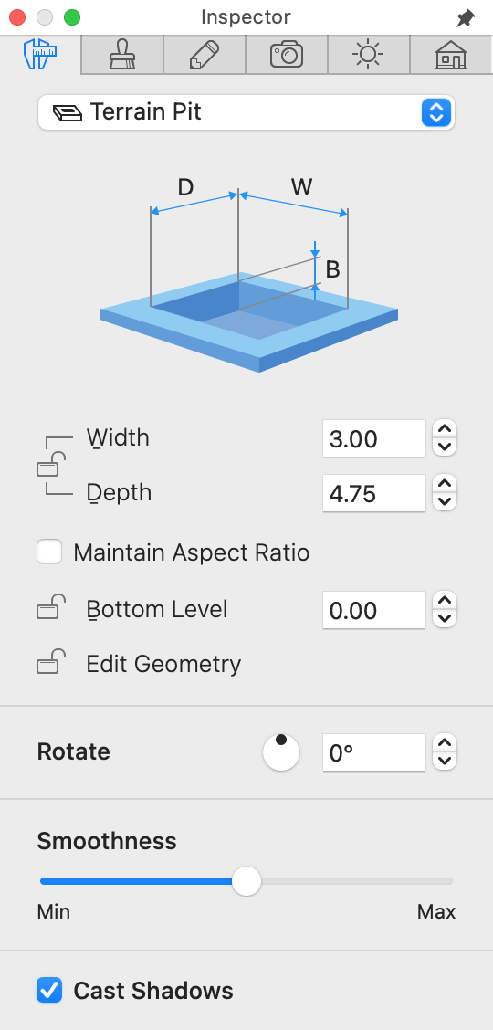
The Width and Depth properties indicate the dimensions of either rectangular pit or bound of polygonal pit. To resize an object proportionally, select the Maintain Aspect Ratio option.
The Bottom Level parameter defines the depth of the specified area measured from the ground level.
The Edit Geometry option allows or disallows modifying the shape of the pit by double-clicking on it. When the option is locked, you can still activate the edit mode by right-clicking on it in the 2D view and choosing Edit Contour.
The Rotate controls let you rotate a pit around its center.
The Smoothness slider changes how curved sides of an object look in 3D. At the Min position, the 3D shape is approximated with a smaller number of larger facets. This improves the program performance but makes the shape less accurate.
The Cast Shadows option lets you control whether the object should cast shadows. Notice that shadows of some flat objects may make almost no difference to the 3D scene. Deactivating such shadows can improve the rendering speed.