Modeling the Terrain
Creating a Pathway
In this section, we are going to learn how to create and edit a pathway. The Pathway tool is located in the Site set of tools. This tool is available when the Site layer is activated.
The functionality described in this section is only available in the Pro edition.
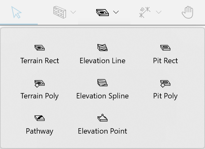
To create a pathway, activate the Pathway tool. Click with the tool where the pathway should begin. To add a corner, click once. Double-click at a point where the path should end.
Parts of the Pathway Object
In the 2D view, the shape of a pathway is defined by the central line that is visible in the edit mode. The width of a pathway is shown by the outline.
The central line passes through points with diamond-shaped handles. These points allow you to change the shape and elevation of the pathway. They are listed in the Inspector.
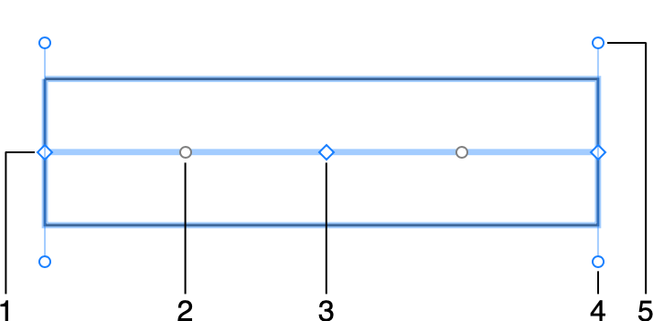
1 - One of the end points.
2 - A circular handle that lets you transform a straight segment into an arc-shaped.
3 - An intermediate point with a diamond-shaped handle.
4 and 5 - Handles that change the pathway's angle at one of its ends.
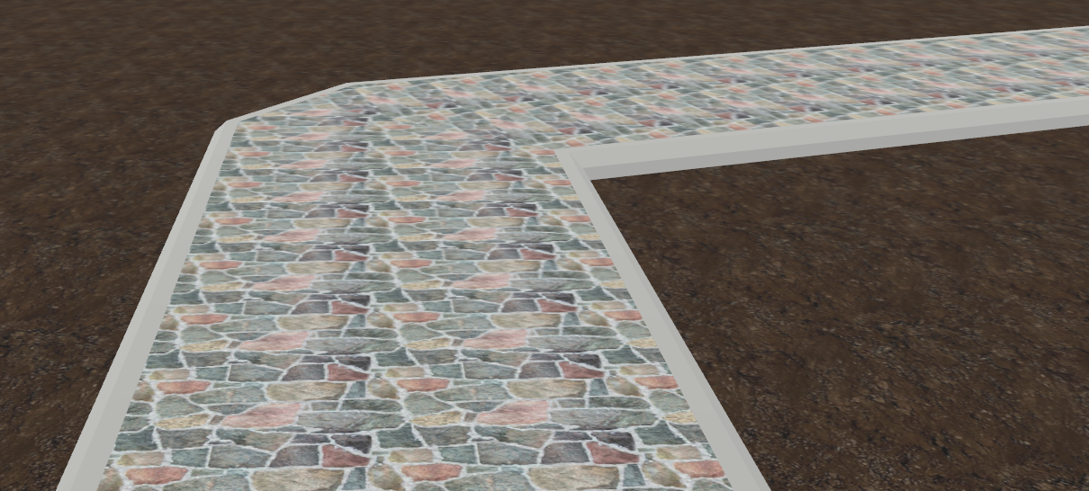
The 3D model of a pathway consists of four parts. We can distinguish them because we can adjust their size or material separately from the other parts.
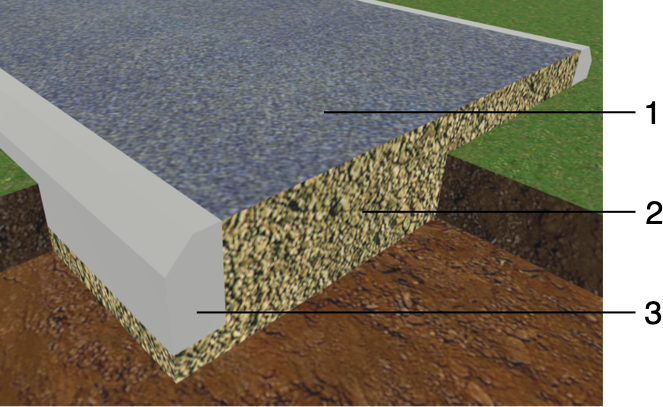
1 - Surface layer.
2 - Base layer.
3 - Curb. There is another one on the opposite side.
Properties of the Pathway Object
Properties of the Pathway object can be found in the Object Properties tab of the Inspector.
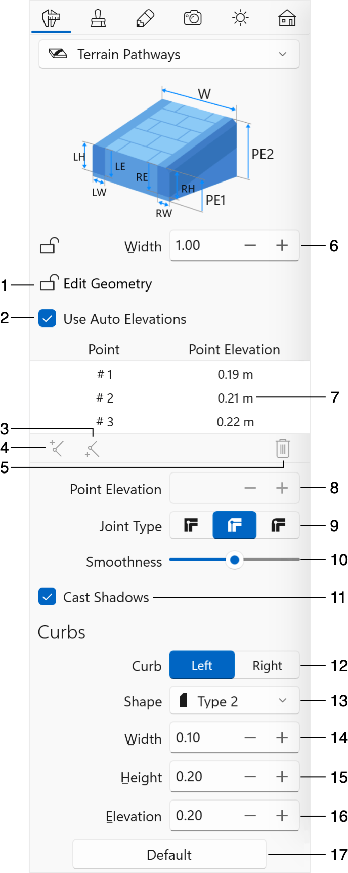
1 - The Edit Geometry option allows or disallows modifying the shape of a pathway.
2 - The Use Auto Elevations option allows the program to set the elevation of points automatically. It is activated by default. If you need to adjust the elevation of a pathway at some point, turn the option off. Then select a point in the list and set a new value into Point Elevation.
3 and 4 - Add a new point before or after a selected one.
5 - Delete a selected point. You can select and delete multiple points.
6 - The Width parameter defines the total width of a pathway, including the curbs.
7 - A list of all points of a pathway with their elevations.
8 - The Point Elevation edit box lets you change the elevation of a pathway at the selected point. This is possible only if the Use Auto Elevations option is deactivated.
9 - The Joint Type option lets you choose the shape of a pathway in a corner.
10 - The Smoothness slider changes how curved segments of a pathway look in 3D. At the Min position, the 3D shape is approximated with a smaller number of larger facets. This improves the program performance, but makes the shape less accurate.
11 - The Cast Shadows option specifies whether a pathway should cast shadow.
12 - Select either the left or right curb to display its properties below.
13 - Select the shape of a curb. To have a pathway with no curbs, select the None option. Curbs on each side of the pathway have individual sets of settings.
14 - The width of a curb.
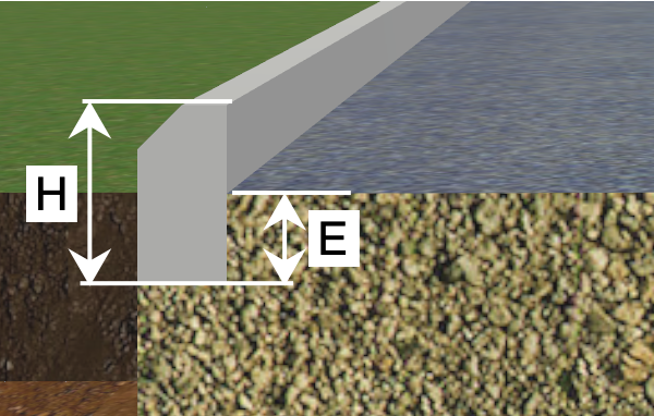
15 - The height of a curb.
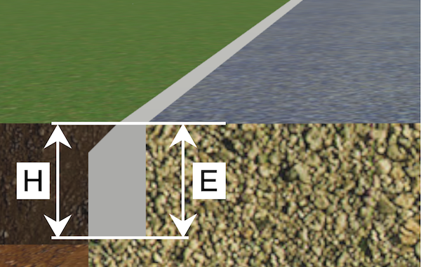
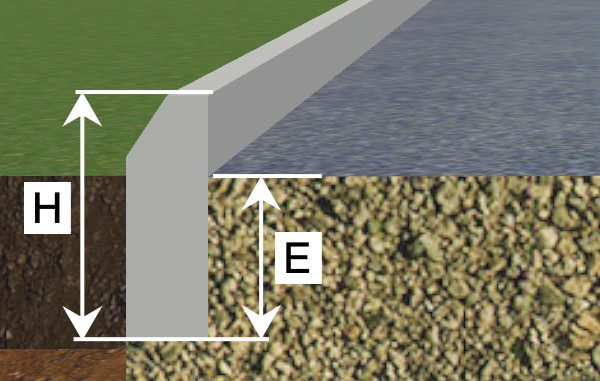
16 - The elevation of a curb. It is measured from the surface of the pathway to the bottom of the curb.
17 - Restore the default settings.
Edit a Pathway
Change the Width
In order to set a new width, use the Width control in the Inspector.
Edit the Shape
To be able to edit a pathway, you should right-click on it and choose Edit Contour from the context menu. You can do the same by double-clicking on the object if the Edit Geometry option is not locked in the Inspector.
When you draw a pathway, you add its start and end points and, possibly, one or more intermediate points to create turns. The locations of all of these points define the shape of the central line. Each point has a diamond-shaped handle. Finally, the created pathway goes along the central line with a specified width.
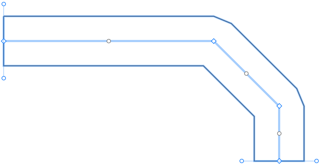
To make the pathway go in a different way, move one or multiple of its points.
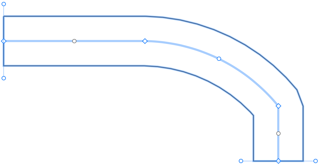
The part of a pathway between two points is called a segment. By default, all segments are straight, but you can make a segment rounded by dragging a circular handle in the middle of the segment.

You can see in the 2D and 3D views that the sides of the rounded segments are made out of a number of straight lines rather than an arc. Such an approximation lets the program render the 3D view slightly faster. If you need to have a perfect arc, move the Smoothness slider to the right.
Add or Delete Points
Points play the key role in editing a pathway. At some moment, you may find out that there are not enough of the original points to shape the path as you want. In this case, you can add more points.
To add a point, double-click on the path for entering the edit mode. Then right-click on the central line at the location where a new point should appear. Finally, select Add Point from the context menu.
To delete a point, activate the edit mode. Right-click on the point and choose Remove Point.
It is also possible to add and delete points using buttons below the list of points in the Inspector.
Choose Corner Type
By default, pathways have corners with the Bevel type.
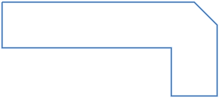
The Inspector lets you apply other shapes using the Joint Type drop-down menu.
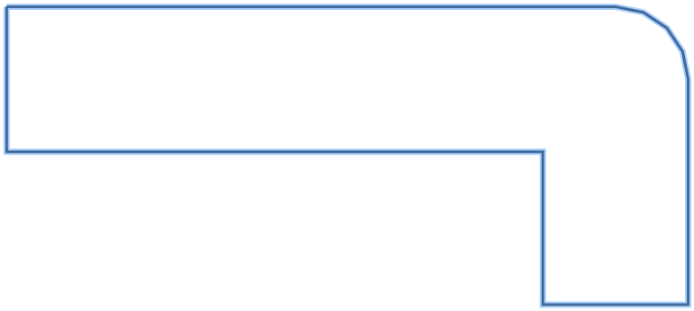
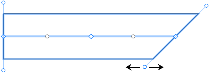
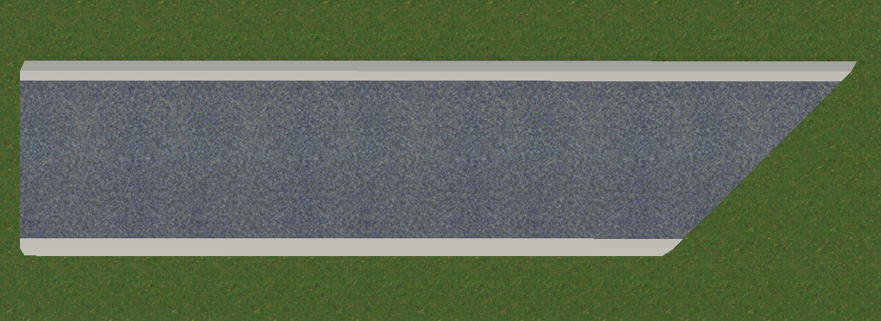
Adjust the Angle at the Pathway End
A pathway may adjoin another pathway at an angle other than 90 degrees. In such a case, you can adjust the angle at one or both ends of the pathway.
Each end point has a direction line with handles on its ends. To change the angle, move one of those handles.
Edit Elevations
When you create a pathway, its elevation is set automatically based on the features of the underlying terrain. Moreover, if you edit the terrain, the pathway will be updated accordingly thanks to the Use Auto Elevations option in the Inspector.
You can customize the pathway by adjusting the elevations of its points. To do this, you should turn the Use Auto Elevations option off. Points with their present elevations are listed in the Inspector. Select a point in the list, and enter a new value into the Point Elevation field.
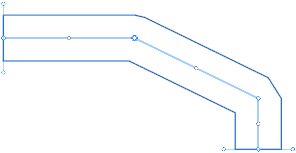
You can also select points in the 2D Plan view directly. Just activate the edit mode and click on a point. A circle will appear around the handle of that point indicating that it is selected.
Change Materials of a Pathway
In order to change the material of any part of a pathway, drag a new material from the Material Library and drop it onto that part. For more details, read the Applying Materials section.