Working with Objects
Ceilings and Floors
Ceilings and floors can be created either manually or automatically. In the second case, we call them "AutoFloor" and "AutoCeiling".
The app creates an AutoFloor and AutoCeiling as soon as you create a room using one of these tools: Room, Straight Wall or Arc Wall. In this context, we use the "room" term when walls create a closed shape, such as a rectangle, on the floor plan. The size and shape of the AutoFloor and AutoCeiling are defined by the shape of the room.
To add a ceiling or floor manually, draw it using the corresponding Ceiling or Floor tool. To activate a tool, open the floor plan, tap on the plus icon in the toolbar, and choose the Building tab in the panel.
To add a rectangular ceiling or floor:
- Activate the Ceiling Rect or Floor Rect tool respectively.
 or
or

- Touch the floor plan and drag the finger aside. This will specify the position of a corner of the floor or ceiling.
- Detach your finger off the screen at the point where the opposite corner should be located.
To add a ceiling or floor with customized shape:
- Activate the Ceiling Poly or Floor Poly tool respectively.
 or
or

- Touch the floor plan and drag the finger to start drawing.
- Detach your finger off the screen to specify the end of the first side of the object.
- Tap on the floor plan multiple times to specify the location of corners of the object's outline. The outline will update every time you add a new corner.
- Tap on the Complete button in the toolbar to deactivate the tool.
You can use the Floor and Ceiling tool to draw a floor and ceiling together one above another. This feature is only available in the Pro edition.
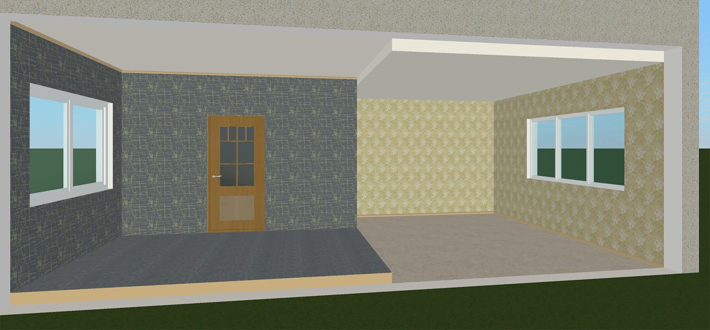
In most cases, you don't have to add floors and ceilings to your project because the app adds them appropriately. Adding a custom floor can be useful when you want to create a terrace, or to make a part of the floor elevated in relation to the rest of the floor.
To delete a custom floor or ceiling, select it on the floor plan or in the Project Tree, and press the Delete button.
The AutoFloor and AutoCeiling cannot be deleted.
Operations common for all object types are discussed in the Basics section. This includes:
The Applying Materials section explains how to apply materials to objects.
The "object" term is used to refer to floors and ceilings later in this section.
Ceiling and Floor Properties in the Inspector
Most of the floor and ceiling parameters are located in the Inspector, where you can change the geometric properties, or set up how the object looks on the floor plan or in the 3D view.
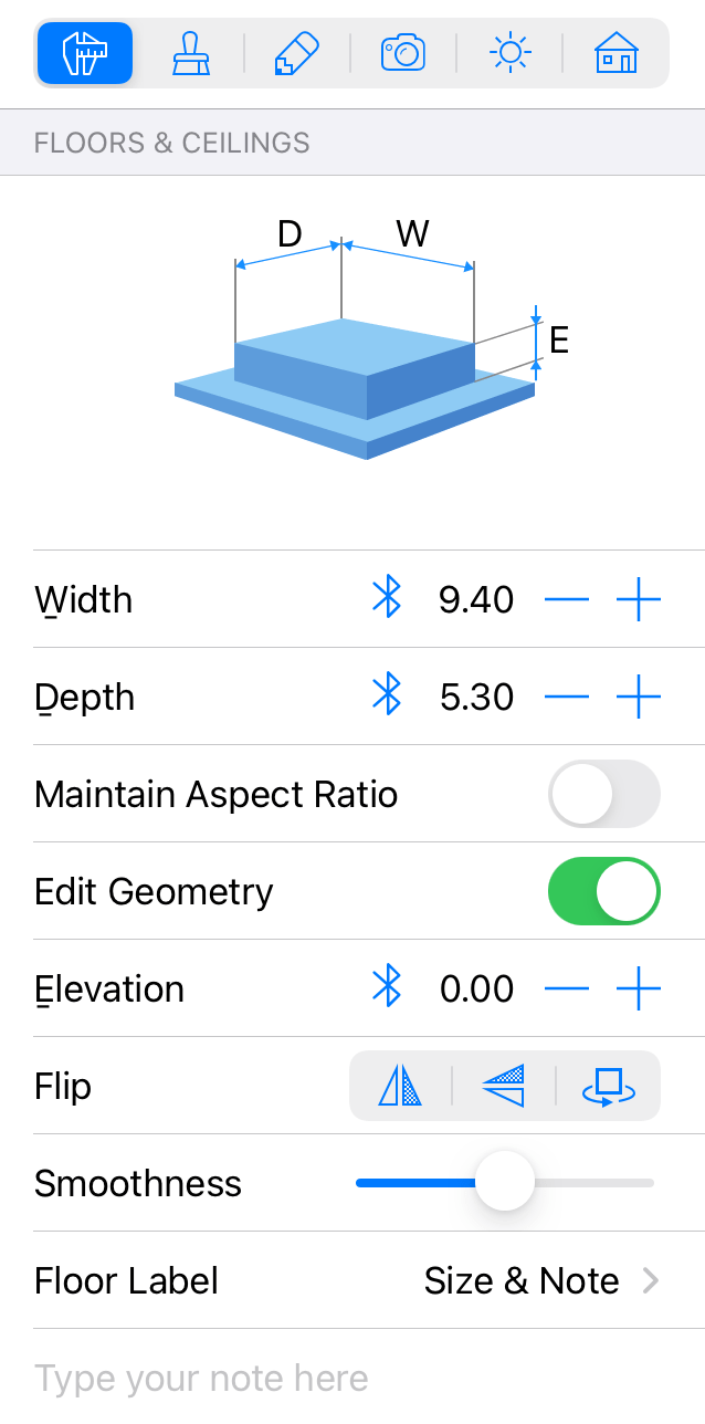
Geometric Properties
The geometric properties of an object can be found in the Object Properties tab of the Inspector.
The default height of a ceiling is defined by the Story Height. Originally, all floors and ceilings on the same story have the same levels. In order to change the level of a floor or ceiling in a specific room, use the Elevation parameter.
You can simulate a split-level house by customizing the Elevation parameter in different rooms.
The other parameters in the Object Properties tab can be changed only if a floor or ceiling was created by a user.
To resize an object, enter new values into the Width and Depth fields. To resize the object proportionally, select the Maintain Aspect Ratio option.
To resize an object on the floor plan directly, drag one of the handles on the object's selection frame. The handles are not displayed when the object dimensions are locked.
To rotate a custom ceiling or floor, use the rotation handle on the floor plan.
The Flip tools let you flip an object horizontally or vertically. The third button rotates the object by 180 degrees.
The Text Label of a Floor
Each floor has a text label. By default, the label is displayed in the middle of the floor. It can show the floor area, dimensions or both. The Floor Label option in the Inspector lets you select whether to display the default information, user's Note, both of them or nothing.
In order to add your own text to the label of any floor, type it in the Inspector below Floor Label. This customizable text is called Note.
The location of the label in the 2D layout can be changed. To do this, just drag it to a new location.
If you place a custom floor over the AutoFloor, the area of the AutoFloor will be decreased by the area of the custom floor.
To show or hide all floor labels in your project, use the 2D tab of the program Settings.
Changing the Shape of a Floor or Ceiling
To modify the shape of a floor or ceiling, long-press on it and choose Edit Contour from the context menu. The resize handles will disappear indicating the contour editing mode. The app will display the object's outline with diamond-shaped handles at corners called "points". To change the shape of the outline, you can move points.
To add a new point, long-press on the contour and choose Add Point. To remove a point, long-press on it and select Remove Point.
The object's shape can also be modified with help of the Combine operations. The outline of the result will depend on the location and shape of the original objects. To combine objects, select at least two of them in the 2D Plan view, bring up the context menu and choose one of the operations.
In the contour editing mode, the app also displays round handles in the middle of each side of the shape. If you move a round handle in one or another direction, the corresponding side will bend inside or outside of the shape creating an arc. While you are changing the curvature of a side, a number near the side changes from 0 (straight line) to 180 (semicircle). One of possible ways to create a circle is to draw a square and bend each side up to 90 degrees.
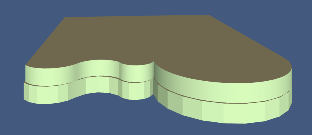
Rounded sides of the object can be displayed in the 3D view as a number of facets or as a smooth surface. To make curvatures more or less smooth, use the Smoothness slider in the Inspector. Higher values may require higher computer performance while the 3D model is rendered. In the picture below, the two identical objects have minimum (at the bottom) and maximum (at the top) level of Smoothness.
When the Edit Geometry option in the Inspector is unlocked, you can activate the editing mode by double-tapping on the object.