Working with Objects
Windows, Doors and Openings
Windows, doors and openings have a similar feature. They can each create an opening in a wall. Therefore, we will use the "opening" term for these objects in this section except when we need to describe the difference between them.
You can insert openings into a wall or roof segment.
If you have imported a 3D model of a door or window, you should set the corresponding object type in the Type & Representation dialog.
Operations common for all object types are discussed in the Basics section. This includes:
The Properties of Objects in 2D section explains how to apply a stroke, fill or pattern to an object using the 2D Properties tab of the Inspector.
The Applying Materials section explains how to apply materials to objects.
Opening Properties in the Inspector
Most of the opening parameters are located in the Inspector where you can change an object's geometric properties, or set up how the object looks on the floor plan or in the 3D view.
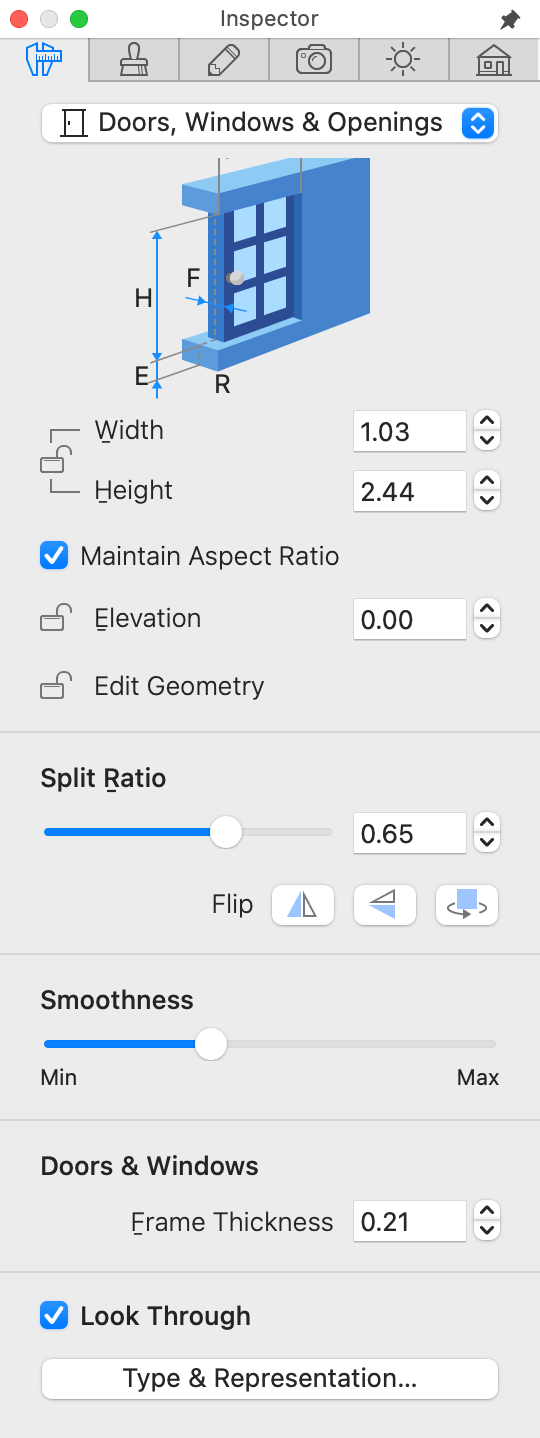
Geometric Properties
The geometric properties of an opening can be found in the Object Properties tab of the Inspector.
To resize an opening, make sure that its dimensions are unlocked in the Inspector. Then enter new values. To resize the object proportionally, select the Maintain Aspect Ratio option.
To resize an opening on the floor plan directly, drag one of the object's handles. The handles are not displayed when the object dimensions are locked.
The Elevation parameter defines how high an object is placed in relation to the default floor level. Since the floor can also be elevated, the object's elevation is calculated from the floor with zero elevation. In a multi-story building, the elevation of objects on each story is calculated from the level of the respective floor.
The Elevation parameter can be locked or unlocked. Locking is useful when you need to move an object horizontally in the 3D view.
The Split Ratio slider changes the position of a window or door in relation to the wall. In this way, you can define how deep a door is in the doorway.
The Flip buttons in the Inspector let you flip or rotate a door or window. This set of tools includes three buttons. All of them affect the object both in the 2D and 3D views. Let's see how these tools work with a door. The left button swaps the left and right sides of the door. The inner side of the door will remain inner. This button can be used when you need to mirror the location of the door handle. The Flip button in the middle swaps the inner and outer door sides. The door handle will stay at the same side of the door. The button on the right rotates the door by 180 degrees.
The Smoothness slider changes how curved sides of the opening outline look in 3D.
The Frame Thickness parameter changes the thickness of a window or door. It can be used to better fit the object to the wall.
The Look Through option lets you define if a door has transparent parts through which one can see objects behind the door. If a door has no transparent parts, you can deactivate this property in order to increase program performance.
Customizing the Shape of Openings
In the Elevation view, you can preview, relocate and modify openings. Since every door and window creates an opening in a wall, they are also displayed in the 2D Elevation view.
The functionality described in this subsection is only available in the Pro edition.
To add a new opening, you can draw it directly on a wall using one of the drawing tools.
To add a rectangular opening, draw it on the wall surface using the Opening Rect tool. Click and hold down the mouse button to start drawing a rectangle. You should then move the cursor to a new position and release the button.
To add a polygonal opening, activate the Opening Poly tool. Click several times on the wall surface to add corners. Double-click in order to specify the position of the last corner of the polygon and deactivate the tool.
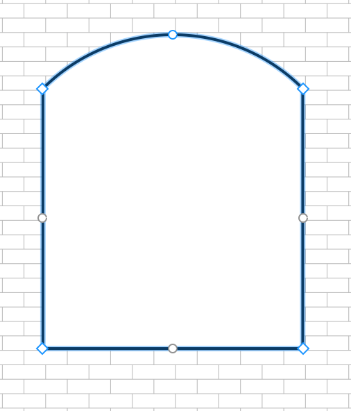
To modify the shape of an opening, right-click on it and choose Edit Geometry from the context menu. The resize handles will disappear, indicating the contour editing mode. The program will display the outline of the opening with diamond-shaped handles at corners called "points". To change the shape of the outline, you can move points.
To add a new point, right-click on the contour and choose Add Point. To remove a point, right-click on it and select Remove Point.
The object's shape can also be modified with help of the Combine operations. The outline of the result will depend on the location and shape of the original objects. To combine objects, select at least two of them in the 2D Plan view, bring up the context menu and choose one of the operations.
In the contour editing mode, the program also displays round handles in the middle of each side of the shape. If you move a round handle in one or another direction, the corresponding side will bend inside or outside of the shape creating an arc. While you are changing the curvature of a side, a number near the cursor changes from 0 (straight line) to 180 (semicircle). One of possible ways to create a circle is to draw a square and bend each side up to 90 degrees. Hold down the Shift key to snap to 15 degree steps.
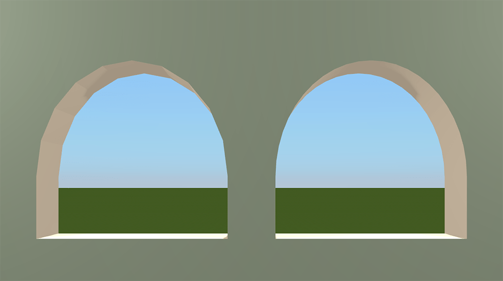
Rounded sides of the object can be displayed in the 3D view as a number of facets or as a smooth surface. To make curvatures more or less smooth, use the Smoothness slider in the Inspector. Higher values may require higher computer performance while the 3D model is rendered. In the picture below, the two identical objects have minimum (to the left) and maximum (to the right) levels of Smoothness.
When the Edit Geometry option in the Inspector is unlocked, you can activate the editing mode by double-clicking on the object.
Be careful with editing of openings which are parts of windows or doors. If you change the opening's shape, for instance, by adding one more corner, the opening will no longer match the object.