Live Home 3D Workspace
The 2D Plan View
The 2D Plan view is used to create a floor plan. You can draw walls, floors and ceilings, and also add objects such as windows or furniture. The 2D Plan view also lets you add text and show dimensions.
To open the 2D Plan view, click the 2D Plan View button in the toolbar.
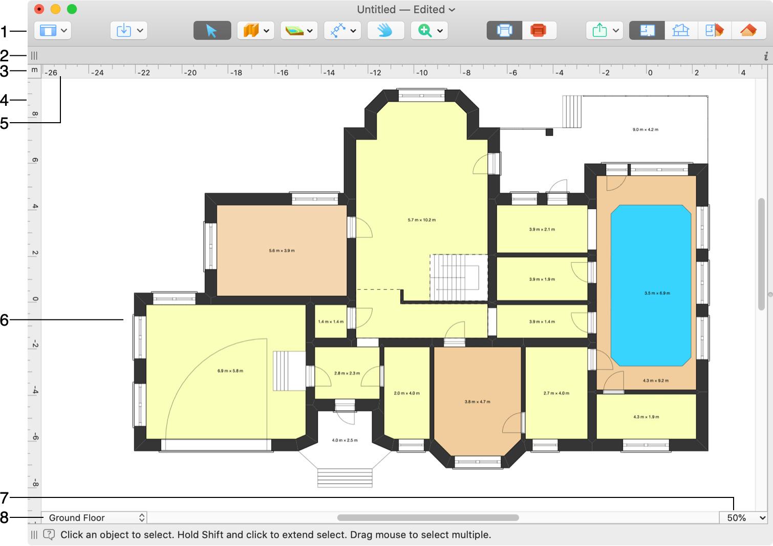
1 – The toolbar. For details, see The Toolbar section below.
2 – The Information bar shows details about the selected object, such as its type, size, elevation and orientation.
3 – The current measurement unit.
4 and 5 – Rulers. For details, see the Rulers section below.
6 – The floor plan editing area.
7 – Change the zoom level of the floor plan.
8 – The story pop-up menu. See the Managing Stories section below.
Only one story can be active in the 2D Plan view at a time. To activate another one, select it in the Building Properties tab of the Inspector or in the story menu.
The 2D Plan view allows you to edit the active story and to see the external walls of the stories above or below it at the same time. To do this, use the View > Show Story Above Current and View > Show Story Below Current menu commands.
You can change the way your project is presented on the floor plan using the 2D Properties tab of the Inspector. You can keep the default look, apply a pattern or color fill to parts of the building, and also use the object’s top view to display it on the floor plan. To convert all objects to the top view look (except for parts of the building), use the 2D Representation button in the toolbar.
The Toolbar

 – The View button lets you control the Library and Inspector.
 – Open the in-app store where you can buy additional content or upgrade the license.
 – Import 3D models from the Trimble 3D Warehouse™ online library or from files on your hard drive.
 – The Select tool for selecting and moving objects.
The Building tool set is used for drawing parts of the building such as walls, ceilings or floors.

 – The Room tool creates a rectangular room with the ceiling and floor.
 – The Straight Wall tool creates straight walls.
 – The Arc Wall tool creates rounded walls.
 – The Floor Rect tool adds a rectangular floor.
 – The Floor Poly tool lets you create a custom-shaped floor.
 – The Ceiling Rect tool creates a rectangular ceiling.
 – The Ceiling Poly tool lets you create a custom-shaped ceiling.
 – The Ceiling Opening Rect tool creates a rectangular opening in the slab of the current story.
 – The Ceiling Opening Poly tool lets you create a custom-shaped opening in the slab of the current story. (Pro edition only)
 – The Floor and Ceiling Rect tool creates a rectangular floor and ceiling of the same shape one under another. (Pro edition only)
 – The Floor and Ceiling Poly tool lets you create a custom-shaped floor and ceiling of the same shape one under another. (Pro edition only)
 – The Building Block Rect tool draws a rectangular building block. It can be used to create things like thresholds or platforms. (Pro edition only)
 – The Building Block Poly tool lets you draw a custom-shaped building block. It can be used to create things like thresholds or platforms. (Pro edition only)
 – The Roof Rect tool adds a rectangular roof. Unlike the AutoRoof, this tool lets you specify the area the roof should take. (Pro edition only)
 – The Roof Poly tool lets you add a roof of other than rectangular shape. Unlike the AutoRoof, this tool lets you specify the area the roof should take. (Pro edition only)
Note that the app creates floors and ceilings automatically as soon as you create a room (a closed shape made out of walls). Therefore, you don’t have to add ceilings or floors in most cases.
Tools in the Site tool set can create a terrain with different elevations and draw a pathway.

 – The Terrain Rect tool adds a rectangular terrain. (Pro edition only)
 – The Terrain Poly tool lets you create a custom-shaped terrain. (Pro edition only)
 – The Pathway tool adds a pathway. (Pro edition only)
 – The Elevation Line tool adds polygonal elevation lines. (Pro edition only)
 – The Elevation Spline tool is a freehand drawing tool for adding elevation lines. (Pro edition only)
 – The Elevation Point tool adds a point whose elevation you can change. (Pro edition only)
 – The Pit Rect tool adds a rectangular pit. (Pro edition only)
 – The Pit Poly tool lets you create a custom-shaped pit. (Pro edition only)
The Auxiliaries tool set contains tools that add dimensions, text annotations, cameras, movie tracks and guidelines.

 – The Dimension tool lets you measure the distance between specified points.
 – The Annotation tool adds text boxes for typing or pasting text.
 – The User Camera tool adds cameras.
 – The Movie Track tool adds movie cameras in order to create a movie track.
 – The Insert Auto Dimensions tool shows the size of wall segments. Also, it shows the size of openings and the distance from openings to corners.
 – The Remove Auto Dimensions tool deletes all automatically added dimensions.
 – The Add Horizontal Guide tool adds a horizontal guide line. By default, it passes through the center of the 2D view.
 – The Add Vertical Guide tool adds a vertical guide line. By default, it passes through the center of the 2D view.
 – The Pan tool lets you grab and scroll the floor plan with the mouse.
 – The Zoom button lets you choose the Zoom In or Zoom Out tool.
 – 2D Representation mode. Use outlines to show objects on the floor plan.
 – 2D Representation mode. Use objects’ top view to display them on the floor plan.
 – Export your floor plan, elevation or 3D view to one of social networking sites, or export to your hard disk, or attach to a message.
 – Display the 2D Plan view.
 – Display the 2D Elevation view. (Pro edition only)
 – Display the 2D and 3D views together in the Split Mode.
 – Display the 3D view.
The tools in the Building tool set (Room and others) and in the Auxiliaries tool set (except for the Movie Track) have two active modes: standard and permanent. When you click a tool once, it activates in the standard mode. As soon as you add the corresponding object, the tool becomes deactivated and the Select tool becomes active.
Upon a double-click (or a second click on an already activated tool), the tool switches to the permanent mode. After adding a corresponding object, the tool stays active and you can continue working with it. This is useful if you need to add, for instance, several cameras. To deactivate the tool, click the Select or another tool.
To customize the toolbar, right-click it and select the Customize Toolbar… command.
Rulers
The 2D view can display rulers that can help you evaluate distances and object’s sizes. To show or hide the rulers, use the View > Show Rulers (Cmd-R) menu command or the View button.
The current measurement unit is indicated in the corner of the rulers. To choose a different unit, click it and select one from the menu that opens. This menu also has a command that opens the Project Settings with additional options.
When you move an object with the mouse in the 2D Plan view, the rulers can display rulerlines. Rulerlines are thin lines that show the coordinates of left, right, top and bottom object edges on the rulers. Rulerlines move along with the object. To show or hide rulerlines, use the View > Show Rulerlines menu command.
Managing Stories
The story pop-up menu in the lower left corner of the 2D Plan view lets you work with stories. The same functionality can be found in the Inspector.
The upper section of the menu lists the stories present in the project and the Site. A tick mark marks out the currently active story. To activate another one, click it in the list.
The Add Story Above Current and Add Story Below Current commands in the lower section let you add a new story to the project.
The Mark Current Story as Ground command turns the story with a tick mark in the list to the ground story.
The Delete Current Story command removes the active story together with objects located on it.